Equipment Location Plan
A Plot General Arrangement Drawing or Equipment Location Plan is a drawing created to show the location of equipment relative to other pieces of equipment. It is drawn in a “plan” view which is above the equipment looking down. The basis for an equipment location plan comes from the Equipment Index, which is usually created by a process or mechanical engineer.
Equipment Location Plan Index
- Reasons for Equipment Location Plan
- Information on Plot General Arrangement Drawing
- Example of an Equipment Location Plan
The spacing between equipment is shown on the drawing as a center line to center line. This is because during the development of the equipment location plan, the physical sizes of the equipment may not be known yet.
Reasons for Equipment Location Plan
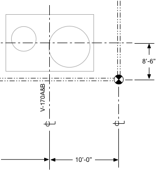 Water Softening Skid showing datum
- Economics - When laying out equipment, keep in mind that the most economic design is one where the amount of piping between equipment is minimized. It is up to the engineer and designer to keep economics into account when laying out equipment.
- Level of Detail - When showing equipment on an equipment location plan, equipment details don’t need to be shown. Initially, the equipment physical size is estimated by the designer and is refined as more information is made available in the design process.
- Normal Operation - Never underestimate or undervalue the input of plant operators, tradespeople and other stakeholders. These are the people that know how to install and operate the equipment better than any engineer or designer.
- Maintenance & Repair - Shell and tube heat exchangers need room to remove the tubes from the shell to perform maintenance. During a normal facility’s life, all equipment will require some type of maintenance and inspection. Be sure to leave enough room for equipment that is needed to clean the equipment for inspection.
- Access Requirements - Ensure there is sufficient room for trucks and vehicle traffic to pass through. Whenever possible, try to avoid dead end roads. Not only is this important for access but in the event of an emergency, will help prevent vehicles being trapped in the plant.
- Process Considerations - The location of equipment may need to be dictated by pressure or temperature drop limitations. For example, pumps should be located to maximize NPSH. The distance from an adjustable speed drive (ASD) to the motor usually needs to be less than a certain distance.
- Electrical Design & Maintenance - Over the course of the facility’s lifetime, electrical motors will likely need to be replaced. Equipment spacing should allow for a reasonably sized crane to access each motor. If ancillary equipment is connected to the motor, like oil coolers or air conditioners, there should be enough room to set the equipment nearby without having to move the crane.
- Spare Capacity and Facility Upgrades - If only a portion of the facility is being installed as part of the project, space left for future equipment or facility upgrades should be shown.
- Equipment Grouping - In the design of a new plant, it might make sense for groups of equipment to be located together. It might make more sense to group several pieces of similar equipment together in a train.
- Hazardous Materials - If there are hazardous materials being produced or stored, containment requirements may require certain pieces of equipment being next to each other.
Information on Plot General Arrangement Drawing
- Fixed, Established Datum Point - If there are multiple design teams working within a single plant, a datum should be agreed upon early in the design process. When selecting a datum, it should be a fixed location that will not change throughout the life of the plant. Not having a common, fixed datum can lead to a multitude of issues further in the design process.
- North Arrow - Like the datum, plant north should be determined early in the design process.
- Scale - Until the design is fully firmed up, the drawing might be marked “No Scale” or “Not to Scale” even if it is drawn to scale. This prevents incorrect or premature dimensions being communicated to other disciplines.
- Battery Limits or Plant/ Facility Boundaries - For large, greenfield facilities, battery limits are the location where custody of design is transferred to another designer.
- All major pieces of equipment & equipment list
- Major structures and buildings
- Roads, access ways
- If there are multiple levels such as within a compressor building, power plant or offshore platform, each level should be represented.
Example of an Equipment Location Plan
An example of a Plot General Arrangement drawing is shown below. This drawing is an example of a project being planned in an existing facility. Original drawings for this plant were not accessible or able to be located. The customer elected only to have the new equipment locations shown. For greater detail, click the drawing. If your screen resolution is too low, try clicking here to open the picture in a new tab or window.
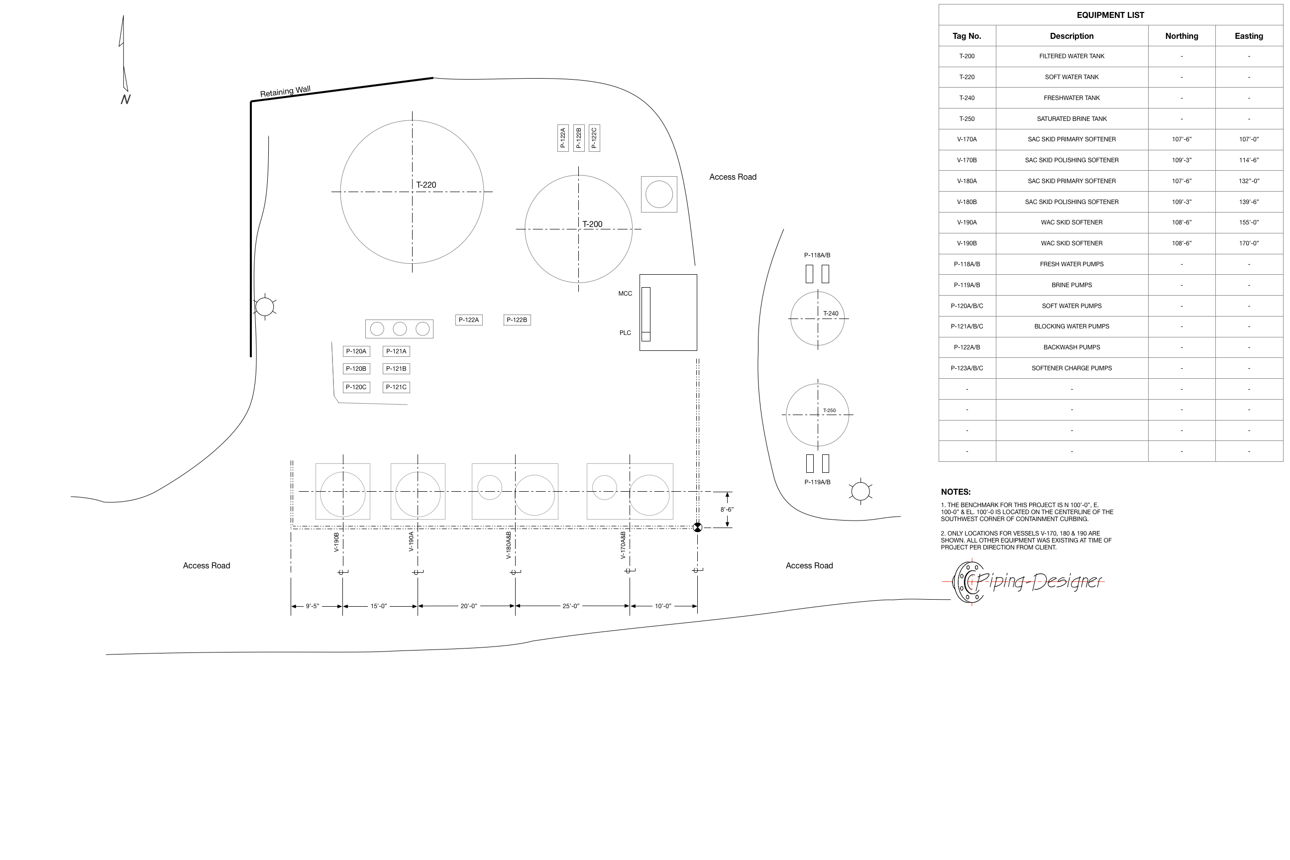 Equipment Location Plan - Water Softening Facility
![]()