Hazardous area classification drawing (also known as an area classification drawing) outlines the classifications of areas where flammable liquids, gasses or vapors are handed, processed or stored. It is created based on input from the Process Flow Diagrams, Piping & Instrumentation Diagrams and the Equipment Location Plan. The intent of the drawing is to communicate to engineers, operators and contractors information on the hazardous material that may be present and the probability that it is in the atmosphere. This knowledge allows for engineers and designers to select the right equipment and for contractors to know how to properly install the equipment.
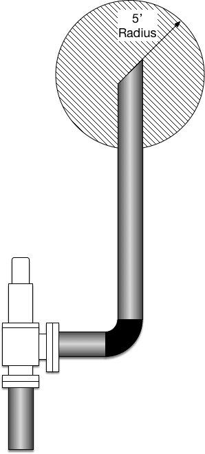 Example of a classified area on a pressure relief valve, PRV
In the United States, the most common way of classifying areas is specified in NFPA 70 - National Electric Code. In the oil and gas industry, API RP500 (Classification of Locations for Electrical Installation at Petroleum Facilities Classified as Class I, Division 1 and Division 2) is commonly followed. However, it should be noted that in the scoping section of API RP 500, it very clearly states that they follow the methods described NFPA 79 (NEC).
It should be noted that an area classification plan does not take into account catastrophic failures of a piece equipment, such as a tank. While these are not considered in the initial development of a hazardous location plan, they should be considered during the Process Hazard Analysis (PHA) or the Hazard and/or Operability Study (HAZOP).
Area Classifications, Divisions, Groups
Area classifications are broken into three categories, Class I, II and III which apply to flammable gasses, flammable dusts and fibers, respectively. Each of these classifications are split into two Divisions:
Division 1 (Div 1) - Locations where flammable or ignitable concentrations of gas, dust or fibers are expected to be present during normal operation. Examples of this might be an open sump or cellar where heavy gasses can accumulate.
Division 2 (Div 2) - Locations are areas where flammable or ignitable concentrations of gas, dust or fibers can accumulate during abnormal conditions. An example of this would be the area around a tank where the pressure safety device vents to atmosphere. While gas is usually not present, when the valve is venting, gas could be present.
NEC Division System Gas & Dust Groups
|
||
| Area | Group | Representative Material |
| Class I, Division 1 & 2 | A | Acetylene |
| B | Hydrogen | |
| C | Ethlene | |
| D | Propane | |
| Class II, Division 1 & 2 | E | Metal Dusts (e.g. magnesium), Division 1 only |
| F | Carbonaceous dusts (e.g. carbon & charcoal) | |
| G | Non-conductive dusts (e.g. flour, grain, wood & plastic) | |
| Class III, Division 1 & 2 | None | Ignitible fibers/ flyings (e.g. cotton, lint, flax, rayon) |
Area Classification Information on a Hazardous Areas
Area classification drawings should be prepared in the following way:
- The classification and extent of each area shall be shown with major structures and equipment indicated.
- Drawings shall provide plan views and sectional views, as required, to clarify area classification.
- All equipment that is considered a source of flammable liquid, gas or vapor must be shown on the drawings. Each source shall be identified by equipment number, the flammable materials handled, flash points and ignition temperature, and atmosphere groups according to the standards to which electrical equipment is specified. It might make sense to include this information as a table on the drawing.
- Drawings should specify the edition date of the standard used for the classification and note exceptions which have been taken. This is important historical information that may not serve an immediate purpose but will be useful in the future.
Area Classification Applicable Codes
It is important to be familiar with the design codes in the applicable industry and apply them as instructed:
ANSI / NFPA Standards
- NFPA 70 National Electrical Code (NEC)
- NFPA 496 Standard for Purged and Pressurized Enclosures for Electrical Equipment (National Fire Codes, vol. 7)
- NFPA 497 Recommended Practice for the Classification of Flammable Liquids, Gases, or Vapors and of Hazardous (Classified) Locations for Electrical Installations in Chemical Process Areas (Revised and Redesigned from NFPA 497A - 1992 and part of NFPA NFPA 497M - 1991 (National Fire Codes, vol. 11)).
API Recommended Practices (RP)
- API RP 500 Classification of Locations for Electrical Installations at Petroleum Facilities as Class I, Division 1 and Division 2
- API RP 505 Classification of Locations for Electrical Installations at Petroleum Facilities as Class I, Zone 0, Zone 1, and Zone 2
International Electrotechnical Commission (IEC) Standard
- 60079-10 Electrical Apparatus for Explosive Gas Atmospheres - Part 10: Classification of Hazardous areas
- 60079-14 Electrical Apparatus for Explosive Gas Atmospheres - Part 14: Electrical Installations in Hazardous Areas (Other Than Mines)
Area Classification Drawing Example
Using the Equipment Location Plan on another page, classified areas are added. In this example, new equipment is not being installed in the classified area so no further detail is necessary. Most hazardous area location plans will show the size of the hatched area relative to the equipment.

Area Classification API RP 500 Formulas
- API RP 500, Ventilation
- API RP 500, Appendix B - Min. Air Induction Ratio to Achive Adequate Ventilation Using Fugitive Emissions
Area Classification API RP 500 Sections
- Section 6 - Classification criteria
- Section 8 - Recommendations for determining degree and extent of classified locations
- Section 9 - Recommendations for determining degree and extent of classified locations in petroleum refineries
- Section 10 - Recommendations for determining degree and extent of classified locations at drilling rigs and production facilities on land and on marine fixed platforms
- Section 11 - Recommendations for determining degree and extent of classified locations on mobile offshore drilling units
- Section 12 - Recommendations for determining degree and extent of classified locations at drilling rigs and production facilities on floating production units
- Section 14 - Recommendations for determining degree and extent of classified locations at petroleum pipeline transportation facilities
Area Classification API RP 500 Drawings
- API RP 500, Fig. 2 - Adequate ventilation nonenclosed area adjacent to a classified area (See sec. 6.4.1)
- API RP 500, Fig. 3 - Enclosed area adjacent to a classified area (See sec. 6.4.2)
- API RP 500, Fig. 4 - Enclosed area adjacent to a classified area (See sec. 6.4.3)
- API RP 500, Fig. 5 - Enclosed area adjacent to a classified area (See sec. 6.4.3)
- API RP 500, Fig. 6 - Fixed roof flammable liquid storage tank in a nonenclosed adequately ventilated area (See sec. 8.2.1.1.1)
- API RP 500, Fig. 7 - Open top floating roof flammable liquid storage tank in a nonenclosed adequately ventilated area (See sec. 8.2.1.2)
- API RP 500, Fig. 8 - Combustible liquid storage tank in a nonenclosed adequately ventilated area (See sec. 8.2.1.3)
- API RP 500, Fig. 9 - Tank car or tank truck loading and unloading via closed system. Product transfered through dome only (See sec. 8.2.2.1)
- API RP 500, Fig. 10 - Tank car or tank truck loading and unloading via closed system. Product transfered through dome only (See sec. 8.2.2.2)
- API RP 500, Fig. 11 - Tank car or tank truck loading and unloading via closed system. Product transfered through bottom only (See sec. 8.2.2.3)
- API RP 500, Fig. 12 - Tank car or tank truck loading and unloading via open system. Product transfered through top or bottom only (See sec. 8.2.2.4)
- API RP 500, Fig. 13 - Tank car or tank truck loading and unloading via closed system. Product transfered through bottom only (See sec. 8.2.2.5)
- API RP 500, Fig. 14 - Process equipment vent in a nonenclosed adequately ventilated area (See sec. 8.2.3.1)
- API RP 500, Fig. 15 - Instrument and control device vent in a nonenclosed adequately ventilated area (See sec. 8.2.3.2)
- API RP 500, Fig. 16 - Atmospheric vent from a Division 1 area (See sec. 8.2.3.3.1)
- API RP 500, Fig. 17 - Atmospheric vent from a Division 2 area (See sec. 8.2.3.3.2)
- API RP 500, Fig. 18 - Relief valve in a nonenclosed adequately ventilated area (See sec. 8.2.3.4.1)
- API RP 500, Fig. 19 - Marine terminal handling flammable liquids (See sec. 8.2.4)
- API RP 500, Fig. 20 - Adequately ventilated process location with heavier-than-air gas or vapor source located near grade (See sec. 9.2.1.1)
- API RP 500, Fig. 21 - Adequately ventilated process location with heavier-than-air gas or vapor source located above grade (See sec. 9.2.1.1)
- API RP 500, Fig. 22 - Inadequately ventilated process location with heavier-than-air gas or vapor source (See sec. 9.2.1.2)
- API RP 500, Fig. 23 - Adequately ventilated compressor shelter with lighter-than-air gas or vapor source (See sec. 9.2.2.1)
- API RP 500, Fig. 24 - Adequately ventilated process location with lighter-than-air gas or vapor source (See sec. 9.2.2.1)
- API RP 500, Fig. 25 - Inadequately ventilated compressor shelter with lighter-than-air gas or vapor source (See sec. 9.2.2.2)
- API RP 500, Fig. 26 - Inadequately ventilated process location with lighter-than-air gas or vapor source (See sec. 9.2.2.2)
- API RP 500, Fig. 27 - Separators, dissolved air floating (DAF) units, and biological oxidation (See sec. 9.2.3)
- API RP 500, Fig. 28 - Mechanical draft cooling tower handling process cooling water (See sec. 9.2.4)
- API RP 500, Fig. 29 - Drilling rig, adequate ventilation in substructure, and derrick is not enclosed, but is equipped with a windbreak, open top, and open v-door (See sec. 10.4.1.1)
- API RP 500, Fig. 30 - Drilling rig, adequate ventilation in enclosed derrick (open top), and inadequately ventilated substructure (See sec. 10.4.1.2)
- API RP 500, Fig. 31 - Platform drilling rig, adequately ventilated in substructure and inside derrick, several producing wells beneath in an adequately ventilated area (See sec. 10.4.1.2)
- API RP 500, Fig. 32 - Platform drilling rig, adequate ventilation in substructure and inside derrick, several producing wells beneath in an inadequately ventilated location (See sec. 10.4.1.4 and 10.5.1.4)
- API RP 500, Fig. 33 - Mud tank in a nonenclosed adequately ventilated area (See sec. 10.4.2.1, 10.4.3.1 and 10.12.2)
- API RP 500, Fig. 34 - Mud tank in an inadequately ventilated area (See sec. 10.4.2.3, 10.4.3.3 and 10.12.3)
- API RP 500, Fig. 35 - Shale shaker in a nonenclosed adequately ventilated area (See sec. 10.4.5.1)
- API RP 500, Fig. 36 - Desander or desilter in an nonenclosed adequately ventilated area (See sec. 10.4.6.1 and 10.4.7.1)
- API RP 500, Fig. 37 - Desander or desilter in an adequately ventilated enclosed area (See sec. 10.4.7.2)
- API RP 500, Fig. 38 - Degasser vent in nonenclosed adequately ventilated area (See sec. 10.4.7.4)
- API RP 500, Fig. 39 - Flowing well in nonenclosed adequately ventilated area and without a cellar or below grade sump (See sec. 10.5.1.1 and 10.15.3.2)
- API RP 500, Fig. 40 - Flowing well in a nonenclosed adequately ventilated area with an inadequately ventilated cellar or below grade sump (See sec. 10.5.1.2 and 10.15.3.2)
- API RP 500, Fig. 41 - Flowing well in an inadequately ventilated enclosed area (See sec. 10.5.1.4)
- API RP 500, Fig. 42 - Nonenclosed adequately ventilated well on which wireline work is being performed (See sec. 10.5.1.7 and 10.5.1.7.2)
- API RP 500, Fig. 43 - Nonenclosed beam pumping well in an adequately ventilated area without a cellar (See sec. 10.5.2.1.1)
- API RP 500, Fig. 44 - Nonenclosed beam pumping well in an adequately ventilated area with an inadequately ventilated cellar (See sec. 10.5.2.1.2)
- API RP 500, Fig. 45 - Electric submersible pumping well in a nonenclosed adequately ventilated area without a cellar (See sec. 10.5.2.3.1)
- API RP 500, Fig. 46 - Electric submersible pumping well in a nonenclosed adequately ventilated area with a inadequately ventilated cellar (See sec. 10.5.2.3.2)
- API RP 500, Fig. 47 - Junction box in a nonenclosed adequately ventilated area connected to an electric submersible pump (See sec. 10.5.2.3.3)
- API RP 500, Fig. 48 - Hydrocarbon pressure pessel or protected fired vessel in a nonenclosed adequately ventilated area (See sec. 10.6.3.1, 10.6.5.1., and 10.6.7.1)
- API RP 500, Fig. 49 - Ball and pig launching or receiving installation in a nonenclosed adequately ventilated area (See sec. 10.6.6.1.1, and 10.6.6.2.1)
- API RP 500, Fig. 50 - Flammable gas-blanketed and protected water-handeling equipment in a nonenclosed adequately ventilated area (See sec. 10.8, and 10.12.4)
- API RP 500, Fig. 51 - Compressor or pump in an adequately ventilated nonenclosed area (See sec. 10.9.1)
- API RP 500, Fig. 52 - Compressor or pump in an adequately ventilated area (See sec. 10.9.1)
- API RP 500, Fig. 53 - Compressor or pump in an adequately ventilated enclosed area (See sec. 10.9.2)
- API RP 500, Fig. 54 - Compressor or pump in an inadequately ventilated enclosed area (See sec. 10.9.3)
- API RP 500, Fig. 55 - Flammable gas operated instruments in an inadequately ventilated enclosed area with all devices vented to the outside (See sec. 10.11.2.2) (For vents, see sec 8.2.3.3)
- API RP 500, Fig. 56 - Flammable gas operated instruments in an inadequately ventilated enclosed area (See sec. 10.11.2.3)
- API RP 500, Fig. 57 - Open sump in an nonenclosed adequately ventilated area (See sec. 10.12.1, 10.12.2 and 10.13 note 4)
- API RP 500, Fig. 58 - Type 1 open drain system (See sec. 10.13.1.1)
- API RP 500, Fig. 59 - Type 2 open drain system (See sec. 10.13.2.1)
- API RP 500, Fig. 60 - Type 3 open drain system in nonenclosed area (See sec. 10.13.3.1)
- API RP 500, Fig. 61 - Drain system in enclosed area (See sec. 10.13.3.4, 10.13.3.5, and 10.13.3.6)
- API RP 500, Fig. 62 - Type 4 open drain system in nonenclosed area (See sec. 10.13.4.1, 10.13.4.2, and 10.13.4.3, and 10.13.4.4)
- API RP 500, Fig. 63 - Type 4 open drain system in enclosed area (See sec. 10.13.4.5, and 10.13.4.6)
- API RP 500, Fig. 64 - Control panel with flammable gas vented to the inside of the enclosed (See sec. 10.16.3)
- API RP 500, Fig. 65 - Inadequately ventilated control panel with instruments inside (See sec. 10.16.4.1)
- API RP 500, Fig. 66 - Adequately ventilated control panel with instruments inside (See sec. 10.16.4.2)
- API RP 500, Fig. 67 - Drilling rig open derrick (See sec. 11.7.1)
- API RP 500, Fig. 68 - Drilling rig semi-enclosed derrick (See sec. 11.7.2)
- API RP 500, Fig. 69 - Drilling rig derrick fully enclosed (See sec. 11.7.3)
- API RP 500, Fig. 70 - Drilling rig open structure and semi-enclosed derrick (See sec. 11.7.3)
- API RP 500, Fig. 71 - Drilling rig with total containment substructure and semi-enclosed derrick (See sec. 11.8.2)
- API RP 500, Fig. 72 - Drilling rig semi-enclosed substructure and semi-enclosed derrick (See sec. 11.8.3)
- API RP 500, Fig. 73 - Drilling rig enclosed moonpool and semi-enclosed derrick (See sec. 11.8.4)
- API RP 500, Fig. 74 - Mud system processing equipment in adequately ventilated enclosed spaces (See sec. 11.9.1)
- API RP 500, Fig. 75 - Mud system processing equipment in open spaces (See sec. 11.9.2)
- API RP 500, Fig. 76 - Mud tanks in open areas (See sec. 11.9.2)
- API RP 500, Fig. 77 - Open top mud tanks in enclosed or semi-enclosed locations with adequate ventilation (See sec. 11.10.2)
- API RP 500, Fig. 78 - Closed top mud tanks in enclosed or semi-enclosed locations with adequate ventilation (See sec. 11.10.3)
- API RP 500, Fig. 79 - Open mud trough in open space before degasser (See sec. 11.11.1)
- API RP 500, Fig. 80 - Open mud trough in enclosed space with adequate ventilation before degasser (See sec. 11.11.1)
- API RP 500, Fig. 81 - Open mud trough in enclosed space with adequate ventilation downstream of degasser (See sec. 11.11.1)
- API RP 500, Fig. 82 - Open mud trough in open space downstream of degasser (See sec. 11.11.1)
- API RP 500, Fig. 83 - Shale shaker in enclosed or semi-enclosed space with adequate ventilation (See sec. 11.13.1)
- API RP 500, Fig. 84 - Shale shaker in open area with adequate ventilation (See sec. 11.13.2)
- API RP 500, Fig. 85 - Desander or desilter in enclosed or semi-enclosed space with adequate ventilation (See sec. 11.14.1)
- API RP 500, Fig. 86 - Desander or desilter in open area (See sec. 11.14.2)
- API RP 500, Fig. 87 - Discharges of ventilation vents and equipment vents originating in Division 1 areas (See sec. 11.15.1)
- API RP 500, Fig. 88 - Ventilation vents originating in Division 2 areas (See sec. 11.15.2)
- API RP 500, Fig. 89 - Diverter line outlet (See sec. 11.16.1)
- API RP 500, Fig. 90 - Typical floating production storage and offloading unit (FPSO) (See sec. 12.2.1)
- API RP 500, Fig. 91 - Typical tension leg platform (TLP) (See sec. 12.3.1)
- API RP 500, Fig. 92 - Typical spar, caisson, or similar unit (See sec. 12.4.1)
- API RP 500, Fig. 93 - Outdoors - pump or compressor handling flammable liquids or highly volatile liquids (See sec. 14.3.1)
- API RP 500, Fig. 94 - Adequately ventilated building - pump or compressor handling flammable liquids or highly volatile liquids (See sec. 14.3.1)
- API RP 500, Fig. 95 - Inadequately ventilated building pump or compressor handling flammable liquids or highly volatile liquids (See sec. 14.3.1)
- API RP 500, Fig. 96 - Outdoors - piping with valves, screwed fittings, flanges or similar accessories handling flammable liquids or highly volatile liquids. Also covers sampling systems, instrumentation and instrument-sized pumps (See sec. 14.3.2)
- API RP 500, Fig. 97 - Adequately ventilated building - piping with valves, screwed fittings, flanges or similar accessories handling flammable liquids or highly volatile liquids. Also covers sampling systems, instrumentation and instrument-sized pumps (See sec. 14.3.2)
- API RP 500, Fig. 98 - Inadequately ventilated building - piping with valves, screwed fittings, flanges or similar accessories handling flammable liquids or highly volatile liquids. Also covers sampling systems, instrumentation and instrument-sized pumps (See sec. 14.3.2)
- API RP 500, Fig. 99 - Elevated storage tank or pressure vessel (See sec. 14.3.3)
- API RP 500, Fig. 100 - Below grade sump tank and oil-water separator (See sec. 14.3.4)
- API RP 500, Fig. 101 - Below grade vault - piping with valves, screwed fittings, flanges or similar accessories handling flammable liquids or highly volatile liquids. Also covers sampling systems, instrumentation and instrument-sized pumps (See sec. 14.3.5)
- API RP 500, Fig. 102 - Above grade source with closure (See sec. 14.3.6)
- API RP 500, Fig. 103 - Storage cavern (See sec. 14.3.7)
- API RP 500, Fig. 104 - Outdoor - compressor or other source handling lighter-than-air flammable gas (See sec. 14.3.8)
- API RP 500, Fig. 105 - Adequately ventilated building - compressor or other source handling lighter-than-air flammable gas (See sec. 14.3.8)
- API RP 500, Fig. 106 - Inadequately ventilated building - compressor or other source handling lighter-than-air flammable gas (See sec. 14.3.8)
![]()