Media Filter
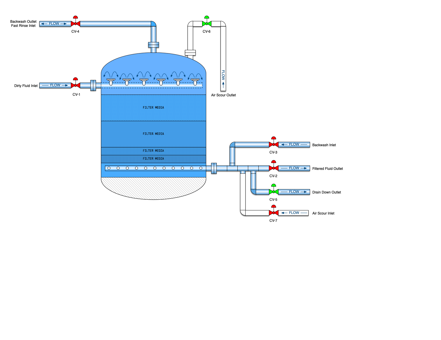
A mechanical filter is a vertical cylindrical vessel that contains some sort filter media. In the oil patch, this will be one to several layers of sand, gravel and/or crushed anthracite. It may also use walnut shells for the filtration media. The filter media is placed on a porous plate to keep the media from washing away. Several layers of gravel are laid on top of the porous plate followed by a layer of sand. Dirty water flows down through the sand and gravel and particulate is removed. The filters are then backwashed to dispose of all the particulate that has accumulated.
Flow rates through multimedia filters can be 3 to 7 gpm/ft2 of vessel area for flow down through the filter media. However, typical oilfield application will limit the flow rate to no more than 6 gpm/ft2 of vessel area. At velocities above this rate, the water can create a "channel" through the filter and reducing the efficiency of the filter.
Downflow filters are just as their name implies. Water enters the filter at the top of the filter and flows down through the media and out the bottom. These are advantageous since they can operate at a higher flow rate. Up flow style filters are much better for handling very dirty water but the flow rates are lower.
Walnut shell filters are used when there is typically very little oil in the production stream. Walnut shells will adsorb the oil and it cannot be backwashed and cleaned. Once the walnut shells get oil on them, they lose their ability to filter and must be disposed of.
Media filters are capable of removing 95 to 99% of particles larger than 2 microns. However, many times, chemical treatment is necessary prior to flowing through the filter.
Sequence of Operation - Down Flow Filters | |||
|---|---|---|---|
| Step # | Sequence Name | Valve Positions (Click for large view) | Reason |
| 1 |
Normal Operation |
|
Normal operation, also known as forward flow, is when the media filter is operating as intended. Flow enters through the inlet and flows down through the media bed. |
| 2 |
Air Scour |
 |
(Optional) This step is sometimes employed to expand the bed to make the backwash more effective. Some operators have found this to be effective. However, many choose to omit this step. |
|
3 |
Backwash |
|
This process done by reversing the flow of water through the filter bed. The purpose of this step is to remove the suspended solids that are trapped in the bed. During backwash, the entire bed lifts and solids exit out the top of the vessel. Ideal backwash rate is usually 12 to 15 gallons per minute per square foot of cross sectional area of the filter. |
|
4 |
Drain Down |
|
(Optional) The drain down step, allows the multimedia to settle before the fast rinse step. The effluent flows to the gravity drain system. The air valve, located on the top of the vessel is open and air enters the vessel. Effluent leaves the vessel to the drain system. |
|
5 |
Fast Rinse |  |
Fast rinse is used with single & multimedia filters. It ensures that the bed is compact and ready for normal operation. This step uses a very high flowrate to create a differential pressure across the bed which then compacts it. |

![]()
Tags: Filtration