Welded Stress and Strain Connections
Welded stress and strain connections, also called welded connections, are structural elements used to join two or more components together in a way that can transmit forces and moments between them. These connections are commonly used in steel structures and other types of metal based construction. The primary purpose of these connections is to transfer loads, such as axial forces, shear forces, and bending moments, from one member to another.
welded connection Index
- Common Types of Welded Connections
- Bar to Plate Welds
- Beam to Plate Welds
- Flat Plate Welds
- Overlapping Plate Welds
- Pipe and Tube Welds
- Plug and Slot Welds
- Structural Shapes to Plate Welds
- Tee Plate Welds
- Rod to Plate Welds
Common Types of Welded Connections
There are several types of welded connections, each designed to address specific load and structural requirements.
- Butt Welds - In a butt weld, two members are aligned end-to-end and joined by welding along the joint. This type of connection is suitable for transmitting axial loads. Depending on the load and design considerations, butt welds can be full penetration (welded through the entire thickness of the joint) or partial penetration.
- Fillet Welds - Fillet welds are triangular welds that join two members at an angle, typically perpendicular or at 45 degrees. These welds are commonly used to transmit shear forces. Fillet welds can be categorized as single fillet, double fillet, or multiple fillet, depending on the number of welds and their arrangement.
- Tee Welds - Tee welds are used to connect one member to the surface of another member, forming a "T" shape. This type of connection is useful for transmitting axial forces and shear forces simultaneously.
- Corner Welds - Corner welds are used to connect two members that meet at a corner. These connections are often used in box shaped or rectangular structures.
- Flare Bevel Groove Welds - These welds are used to connect members with non-parallel surfaces, such as the flanges of I-beams. They provide a larger surface area for welding, making them suitable for transmitting bending moments and shear forces.
- Plug and Slot Welds - These welds involve creating holes in one member and filling them with weld material to join the two members. Slot welds are similar but involve a longer slot-like hole. Plug and slot welds are commonly used for joining thin plates.
The design of welded connections involves careful consideration of factors such as the applied loads, material properties, welding processes, and required safety margins. Engineers must ensure that the welds are capable of transmitting the intended loads without failure. Proper weld sizing, choice of welding process, material compatibility, and inspection methods are critical to the overall integrity of the structure.
It's important to note that while welded connections are widely used, they require careful design and execution to avoid potential issues such as weld defects, material distortion, and premature failure. Proper testing and inspection during fabrication and construction are essential to ensure the quality and performance of welded connections in structural applications.
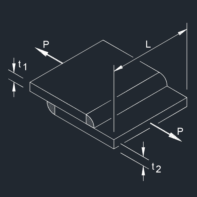
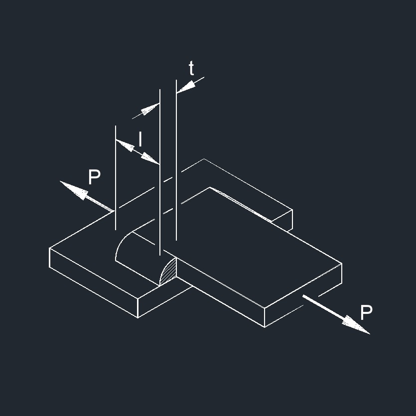
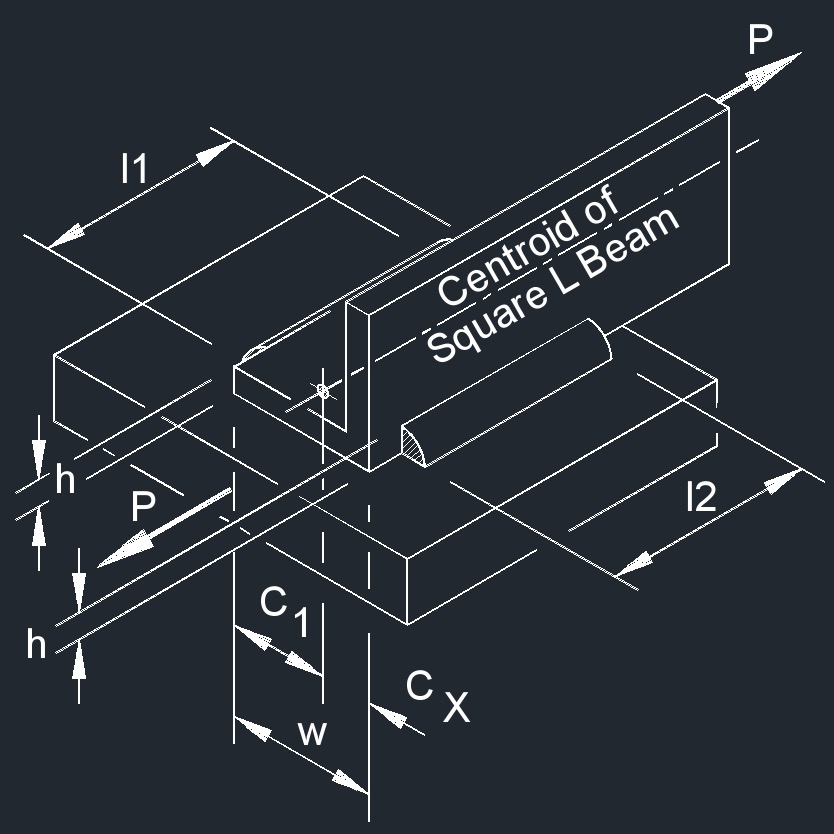
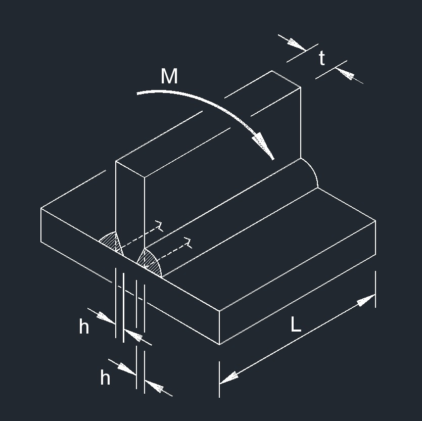
Bar to Plate welds
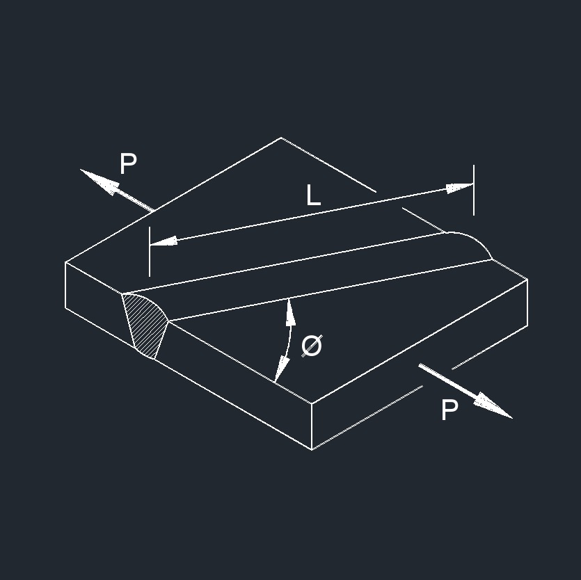
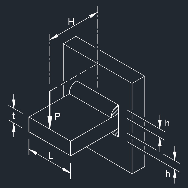
 Applied Force on PJP Fillet Weld
 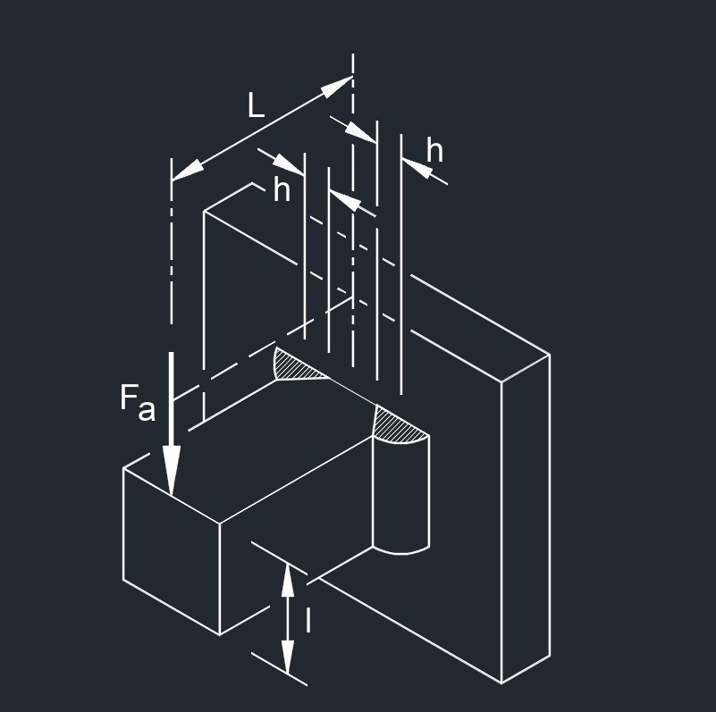 Applied Force on CJP Fillet Weld
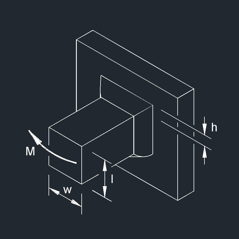
 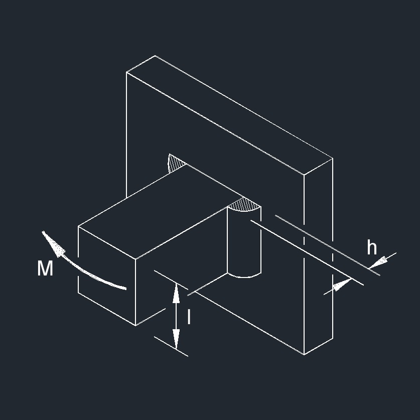 Bending Moment on PJP Fillet Weld
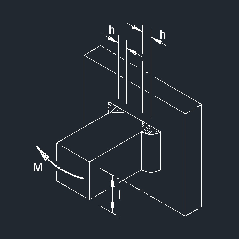 Bending Moment on CJP Fillet Weld
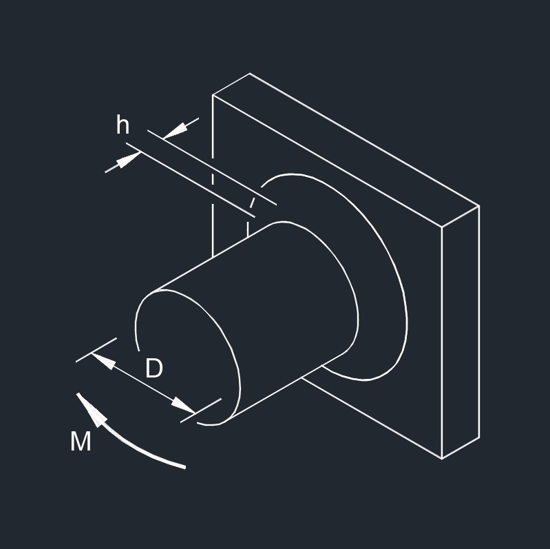
 Bending Moment on PJP Fillet Weld All Around
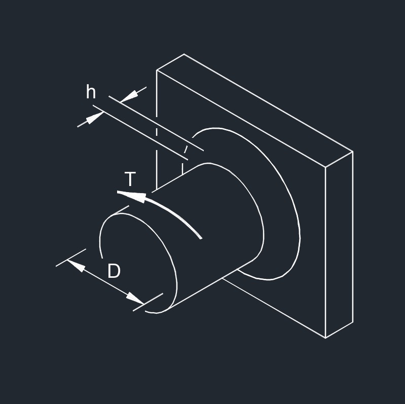
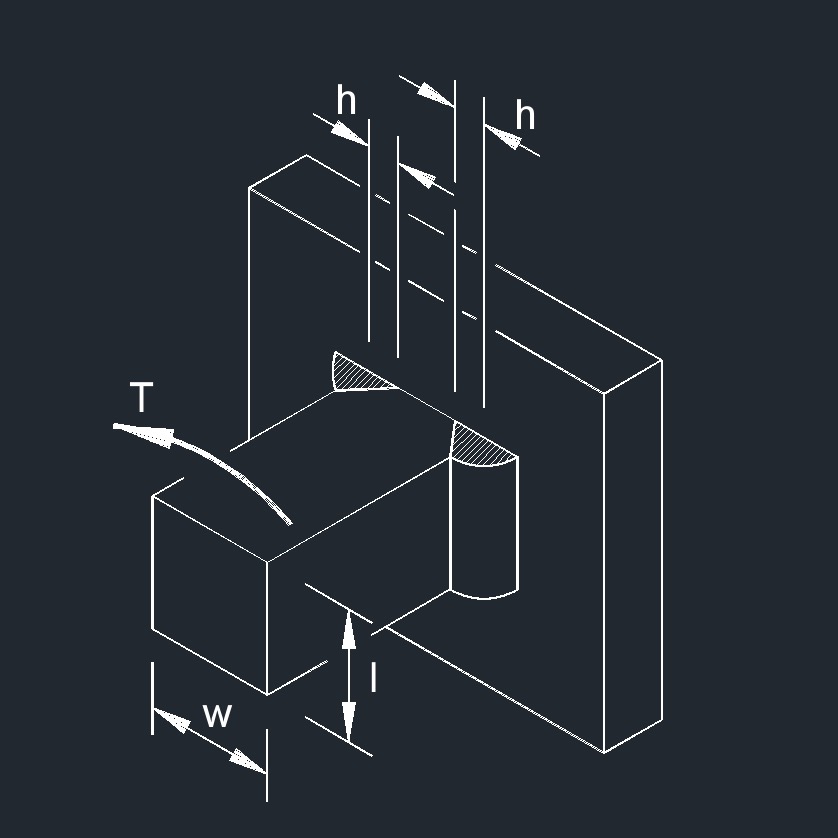 Torsion Moment on CJP Fillet Weld
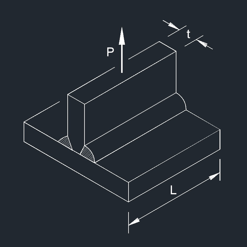
Beam to Plate welds
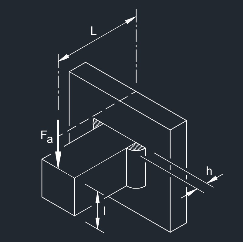
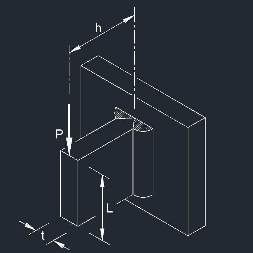 Point Load on CJP Fillet Weld
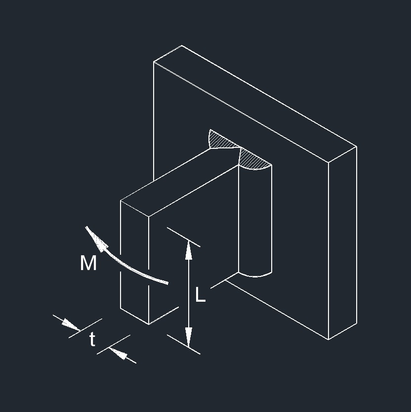 Bending Moment on CJP Fillet Weld
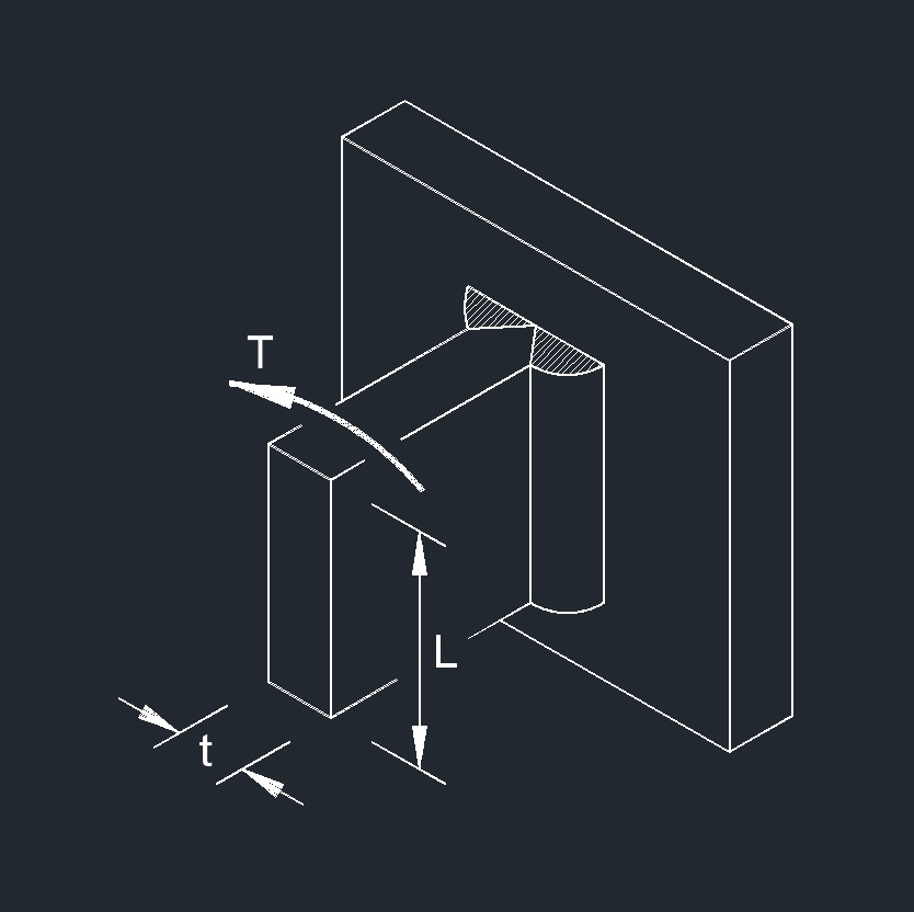 Torsion Load on CJP Fillet Weld
Flat Plate welds
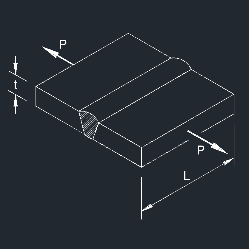 Axial Force on Butt Weld
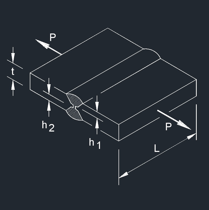 Axial Force on Fillet Weld
 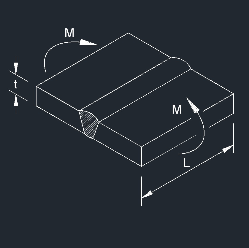 Bending Moment on Butt Weld
 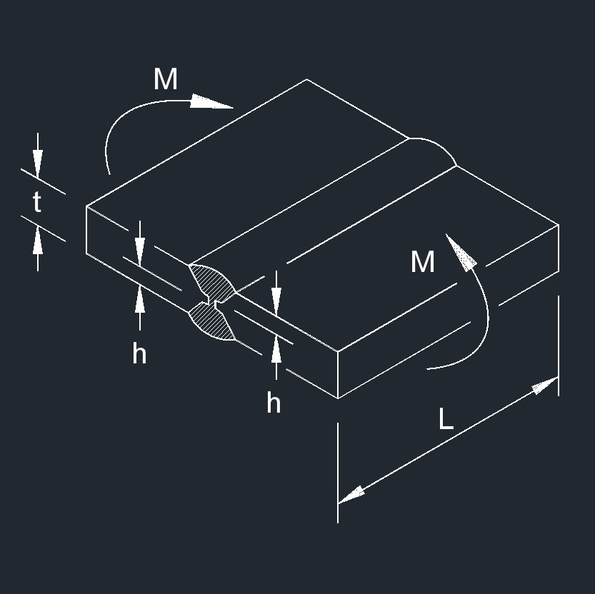 Bending Moment on Fillet Weld
 Axial Force on Angled Butt Weld
 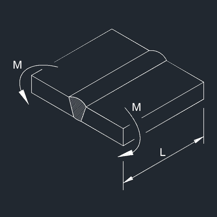 Bending Moment on Butt Weld
 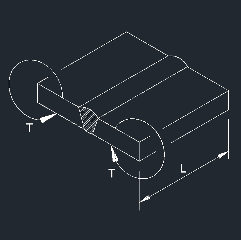 Torsion Moment on Butt Weld
 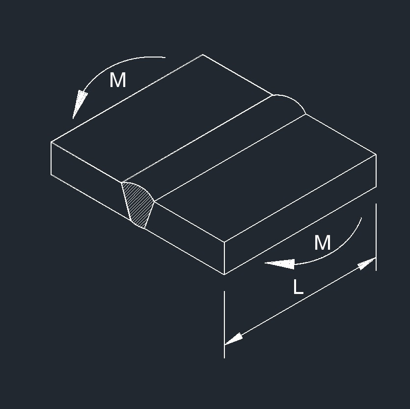 Bending Moment on Butt Weld
Overlapping Plate Welds
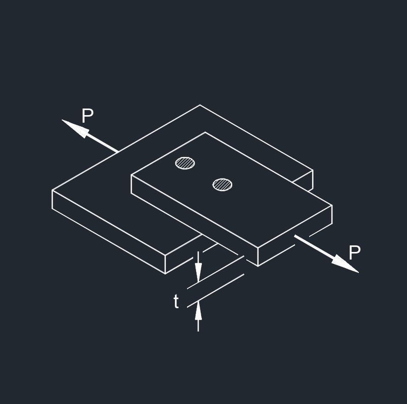
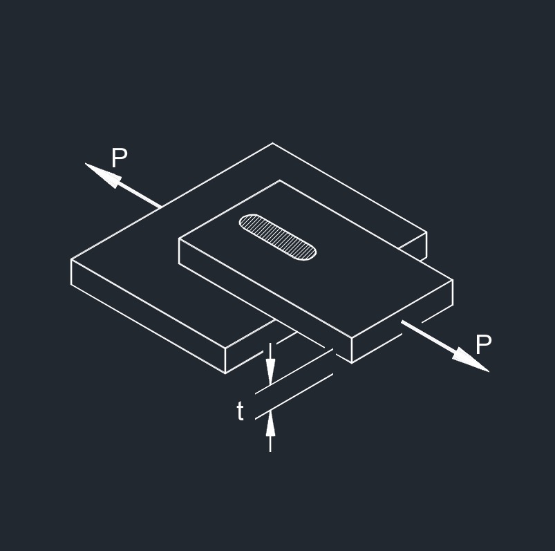
 Axial Force on PJP Fillet Weld, 2 Plates
 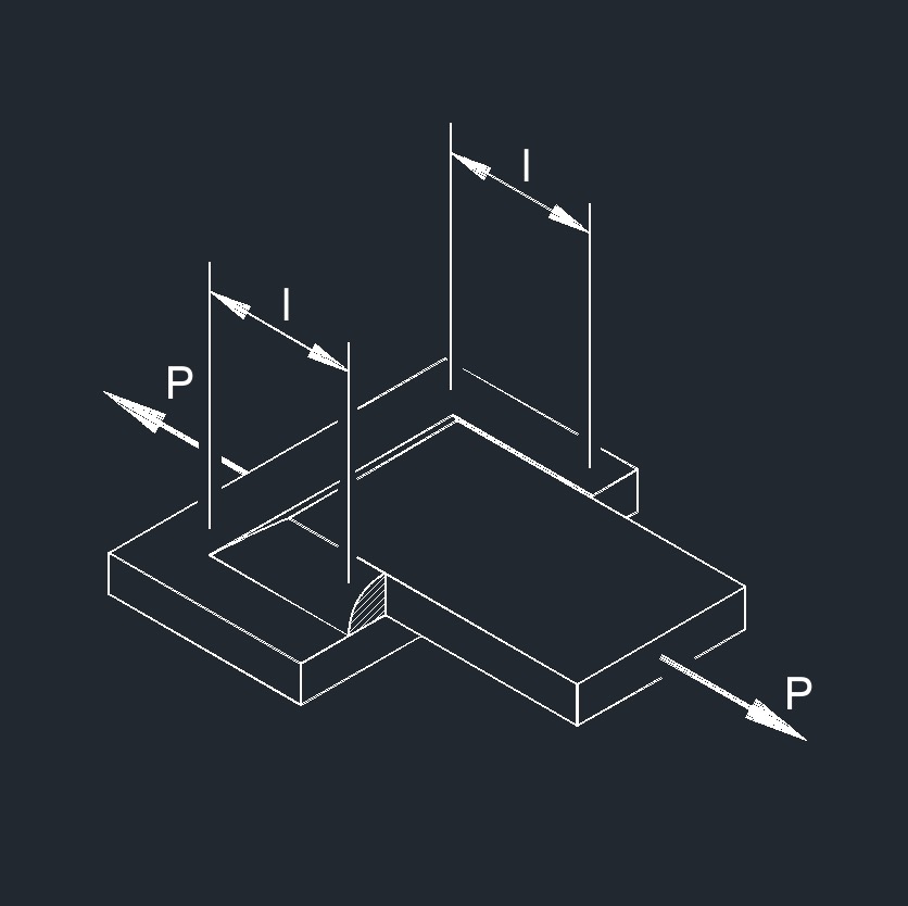 Axial Force on PJP Fillet Weld, 2 Plates
 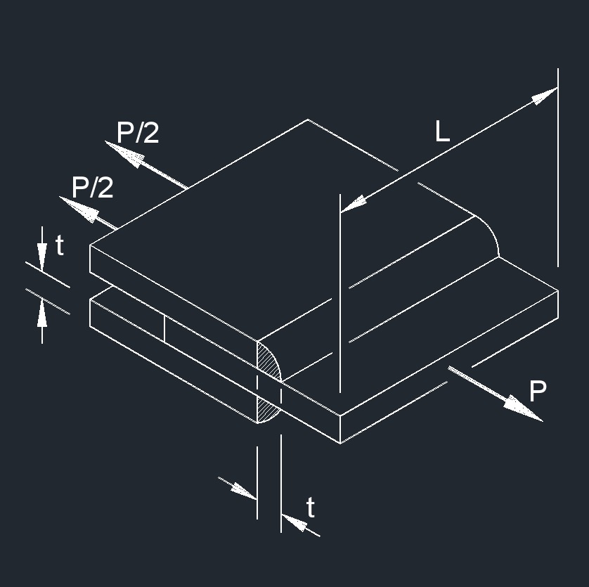 Axial Force on PJP Fillet Weld, 3 Plates
 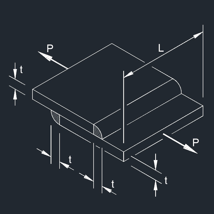 Axial Force on PJP Fillet Weld, 2 Plates
 Axial Force on PJP Fillet Weld, 2 Plates
 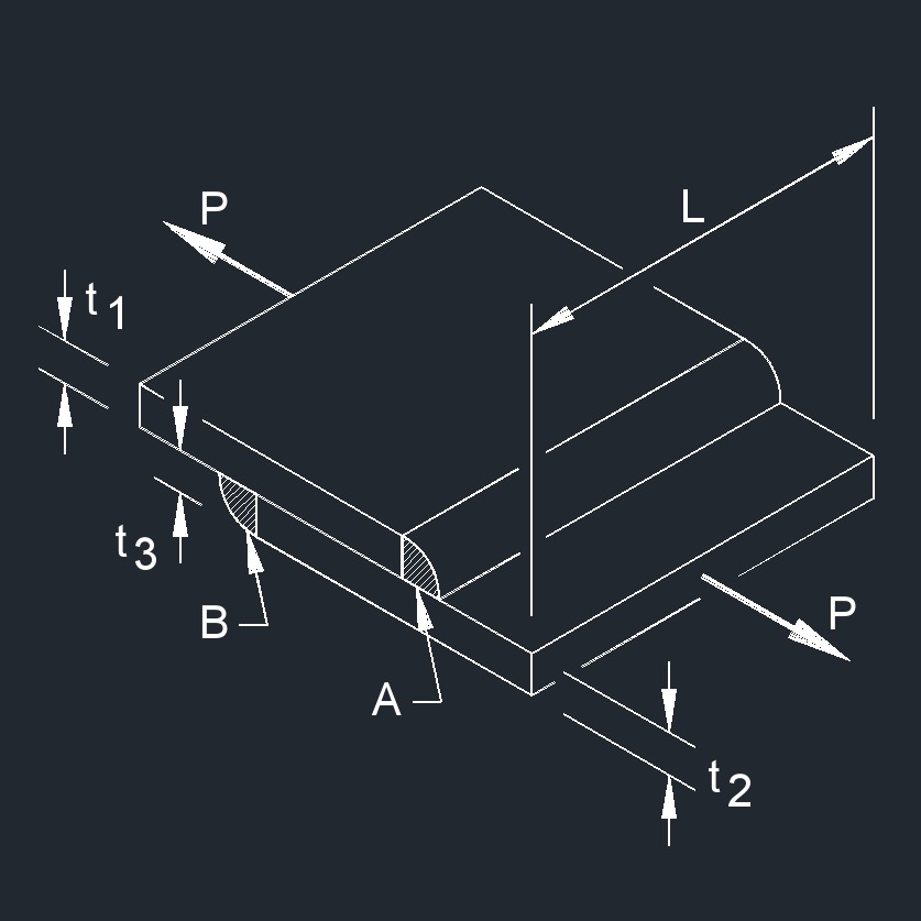 Axial Force on PJP Fillet Welds, 2 Plates
 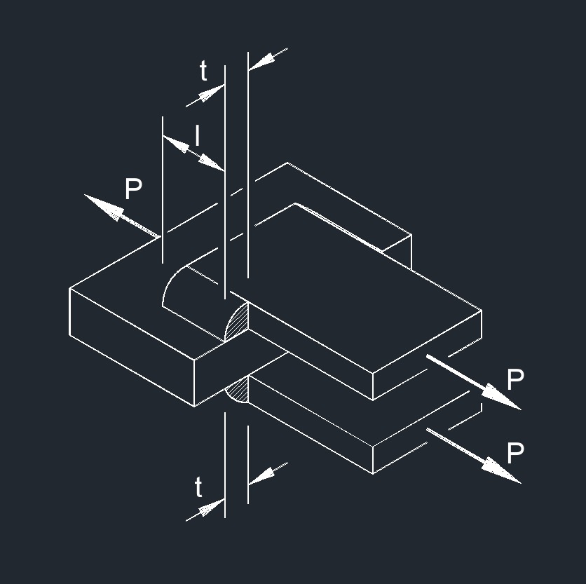 Axial Force on PJP Fillet Welds, 3 Plates
 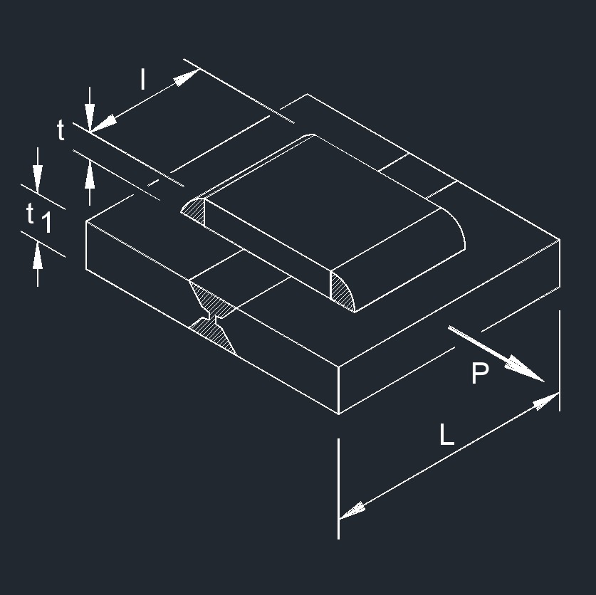 Axial Force on CJP PJP Fillet Weld, 3 Plates
Pipe and Tube welds
 Axial Force on CJP Butt Weld
 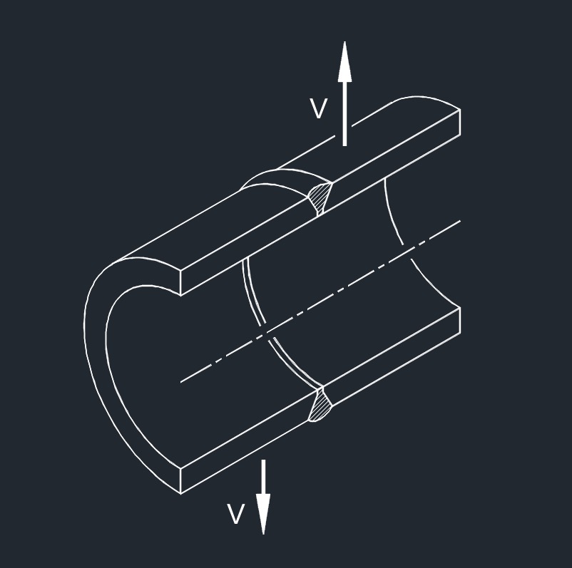 Shear Force on CJP Butt Weld
 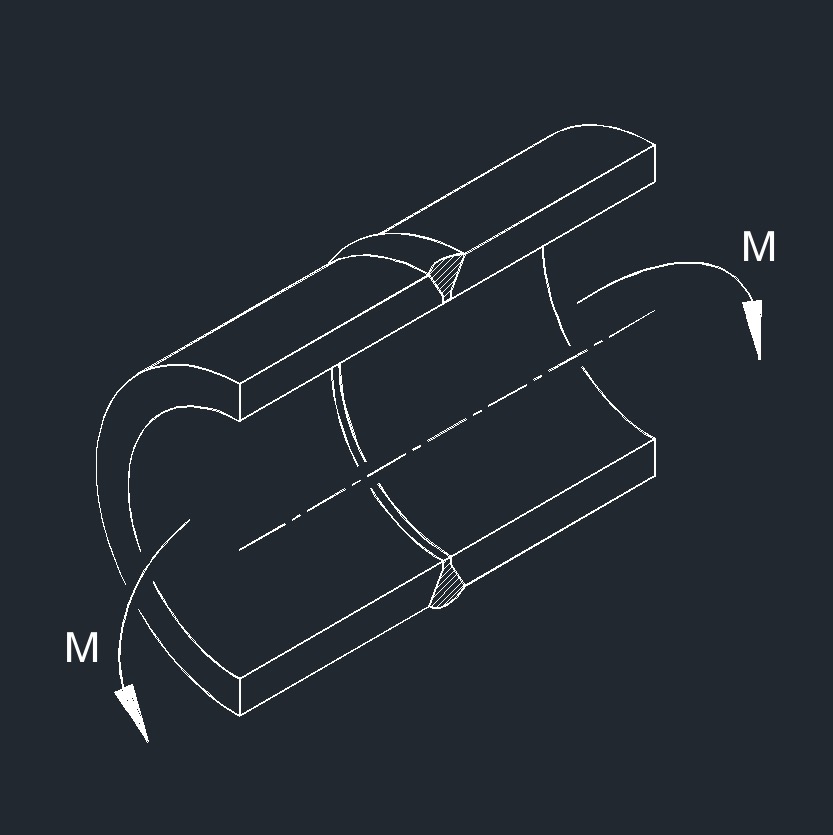 Bending Moment on CJP Butt Weld
 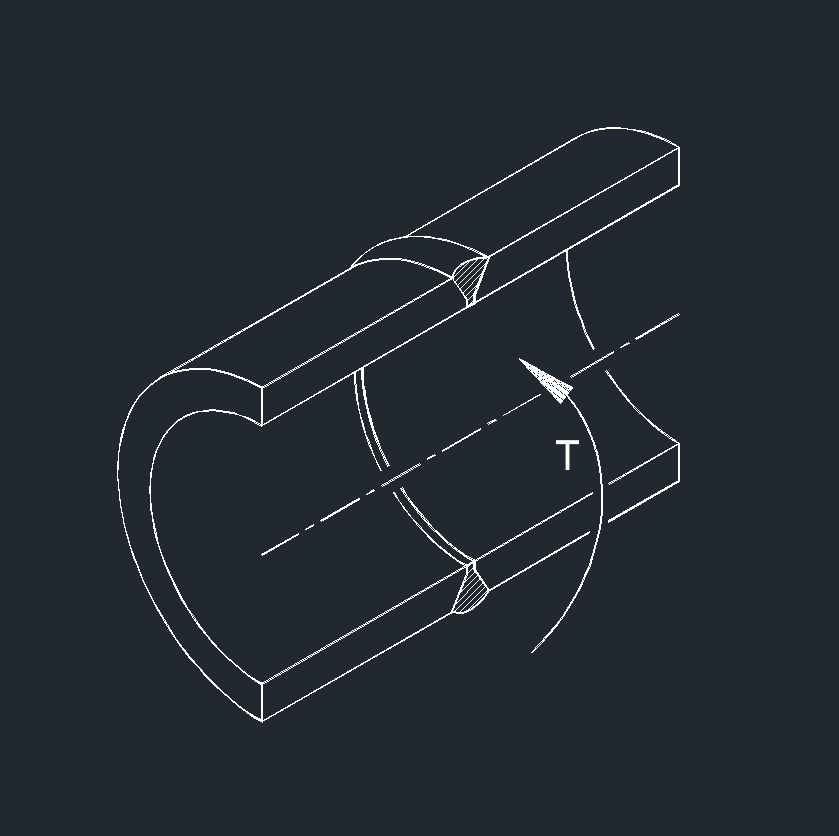 Torsion Moment on CJP Butt Weld
Plug and Slot Welds
Tee Plate welds
 Axial Force on CJP Fillet Weld
 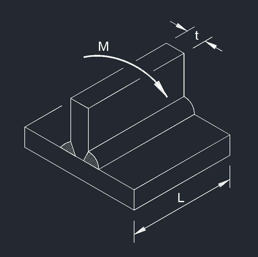 Bending Moment on CJP Fillet Weld
 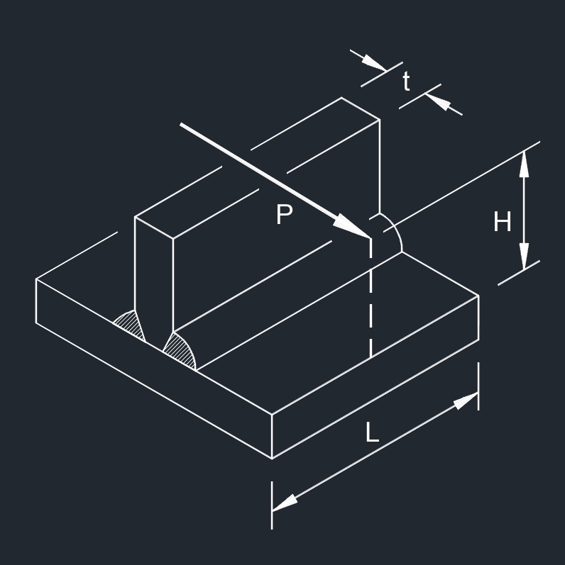 Perpendiculat Force on CJP Fillet Weld
 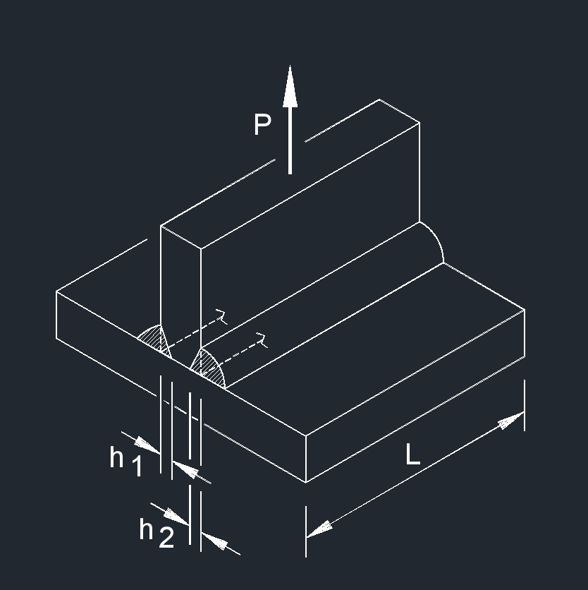 Axial Force on PJP Fillet Weld
 Bending Moment on PJP Fillet Weld
 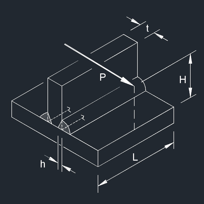 Perpendicular Force on PJP Fillet Weld
 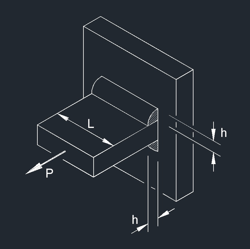 Axial Force on PJP Fillet Weld
 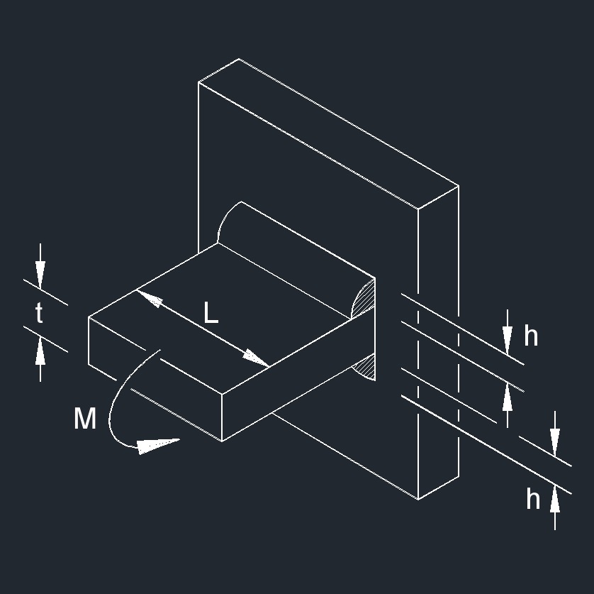 Bending Moment on PJP Fillet Weld
 Perpendicular Force on PJP Fillet Weld