Mechanical Joint Tees - Full Body, AWWA C110, DI (in) | ||||||
|---|---|---|---|---|---|---|
| Pipe Size | Dimensions (in) | Approx. Weight (lb) MJ | ||||
| Run | Run | Branch | E | F | G | |
| * 2 | 2 | 2 | 3.25 | 3.25 | - | 21 |
| * 3 | 3 | 2 | 3.25 | 3.25 | - | 45 |
| 3 | 3 | 3 | 5.5 | 5.5 | 13.5 | 58 |
| * 4 | 4 | 2 | 4.8 | 4.8 | 14.5 | 68 |
| 4 | 4 | 3 | 6.5 | 6.5 | 14.5 | 77 |
| 4 | 4 | 4 | 6.5 | 6.5 | 14.5 | 78 |
| 4 | 4 | 6 | 8.0 | 8.0 | - | 112 |
| * 6 | 6 | 2 | 8.0 | 8.0 | - | 78 |
| 6 | 6 | 3 | 8.0 | 8.0 | 16.0 | 112 |
| 6 | 6 | 4 | 8.0 | 8.0 | 16.0 | 110 |
| 6 | 6 | 6 | 8.0 | 8.0 | 16.0 | 119 |
| 6 | 6 | 8 | 9.0 | 9.0 | - | 158 |
| 8 | 8 | 3 | 9.0 | 9.0 | 17.0 | 155 |
| 8 | 8 | 4 | 9.0 | 9.0 | 17.0 | 157 |
| 8 | 8 | 6 | 9.0 | 9.0 | 17.0 | 175 |
| 8 | 8 | 8 | 9.0 | 9.0 | 17.0 | 199 |
| 10 | 10 | 4 | 11.0 | 11.0 | 19.0 | - |
| 10 | 10 | 6 | 11.0 | 11.0 | 19.0 | 258 |
| 10 | 10 | 8 | 11.0 | 11.0 | 19.0 | 268 |
| 10 | 10 | 10 | 11.0 | 11.0 | 19.0 | 300 |
| 12 | 12 | 4 | 12.0 | 12.0 | 20.0 | 318 |
| 12 | 12 | 6 | 12.0 | 12.0 | 20.0 | 325 |
| 12 | 12 | 8 | 12.0 | 12.0 | 20.0 | 335 |
| 12 | 12 | 10 | 12.0 | 12.0 | 20.0 | 392 |
| 12 | 12 | 12 | 12.0 | 12.0 | 20.0 | 396 |
| 14 | 14 | 12 | 14.0 | 14.0 | 22.0 | 540 |
| 14 | 14 | 14 | 14.0 | 14.0 | 22.0 | 585 |
| * 16 | 16 | 4 | 15.0 | 15.0 | 23.0 | 600 |
| 16 | 16 | 6 | 15.0 | 15.0 | 23.0 | 615 |
| 16 | 16 | 8 | 15.0 | 15.0 | 23.0 | 625 |
| 16 | 16 | 10 | 15.0 | 15.0 | 23.0 | 645 |
| 16 | 16 | 12 | 15.0 | 15.0 | 23.0 | 660 |
| 16 | 16 | 16 | 15.0 | 15.0 | 23.0 | 740 |
| 18 | 18 | 6 | 13.0 | 15.5 | - | 710 |
| 18 | 18 | 8 | 13.0 | 15.5 | - | 674 |
| 18 | 18 | 12 | 13.0 | 15.5 | - | 749 |
| 18 | 18 | 18 | 16.5 | 16.5 | - | 945 |
| 20 | 20 | 6 | 14.0 | 17.0 | - | 849 |
| 20 | 20 | 8 | 14.0 | 17.0 | - | 892 |
| 20 | 20 | 12 | 14.0 | 17.0 | - | 896 |
| 20 | 20 | 16 | 18.0 | 18.0 | - | 1095 |
| 20 | 20 | 20 | 18.0 | 18.0 | - | 1258 |
| 24 | 24 | 6 | 15.0 | 19.0 | - | 1233 |
| 24 | 24 | 8 | 15.0 | 19.0 | - | 1234 |
| 24 | 24 | 12 | 15.0 | 19.0 | - | 1256 |
| 24 | 24 | 14 | 15.0 | 19.0 | - | 1220 |
| 24 | 24 | 16 | 15.0 | 19.0 | - | 1245 |
| 24 | 24 | 18 | 22.0 | 22.0 | - | 1735 |
| 24 | 24 | 20 | 22.0 | 22.0 | - | 1720 |
| 24 | 24 | 24 | 22.0 | 22.0 | - | 1947 |
| 30 | 30 | 6 | 18.0 | 23.0 | - | 2050 |
| 30 | 30 | 8 | 18.0 | 23.0 | - | 2060 |
| 30 | 30 | 10 | 18.0 | 23.0 | - | 2075 |
| 30 | 30 | 12 | 18.0 | 23.0 | - | 2090 |
| 30 | 30 | 16 | 18.0 | 23.0 | - | 2145 |
| 30 | 30 | 18 | 18.0 | 23.0 | - | 2170 |
| 30 | 30 | 20 | 18.0 | 23.0 | - | 2205 |
| 30 | 30 | 24 | 25.0 | 25.0 | - | 2880 |
| 30 | 30 | 30 | 25.0 | 25.0 | - | 2275 |
| 36 | 36 | 6 | 20.0 | 26.0 | - | 2439 |
| 36 | 36 | 8 | 20.0 | 26.0 | - | 2444 |
| 36 | 36 | 10 | 20.0 | 26.0 | - | 2535 |
| 36 | 36 | 12 | 20.0 | 26.0 | - | 2541 |
| 36 | 36 | 14 | 20.0 | 26.0 | - | 2570 |
| 36 | 36 | 16 | 20.0 | 26.0 | - | 2585 |
| 36 | 36 | 18 | 20.0 | 26.0 | - | 2610 |
| 36 | 36 | 20 | 20.0 | 26.0 | - | 2635 |
| 36 | 36 | 24 | 20.0 | 26.0 | - | 2792 |
| 36 | 36 | 30 | 28.0 | 28.0 | - | 3545 |
| 36 | 36 | 36 | 28.0 | 28.0 | - | 3450 |
| 42 | 42 | 24 | 23.0 | 30.0 | - | 3690 |
| 42 | 42 | 30 | 31.0 | 31.0 | - | 4650 |
| 42 | 42 | 36 | 31.0 | 31.0 | - | 4880 |
| 42 | 42 | 42 | 31.0 | 31.0 | - | 6320 |
| 48 | 48 | 24 | 26.0 | 34.0 | - | 4995 |
| 48 | 48 | 30 | 26.0 | 34.0 | - | 5140 |
| 48 | 48 | 36 | 34.0 | 34.0 | - | 6280 |
| 48 | 48 | 42 | 34.0 | 34.0 | - | 8130 |
| 48 | 48 | 48 | 34.0 | 34.0 | - | 8420 |
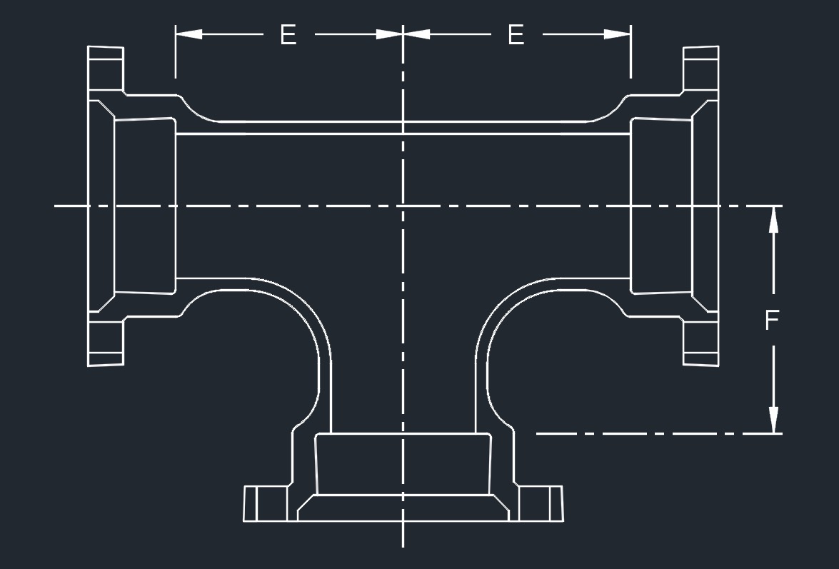 MJ x MJ x MJ - straight, reducing & bullhead
- * These fittings are not included in AWWA C110/A21.10
- For flange dimensions see Flange - ANSI Class 125, C110, DI
- AWWA C110/A21.10 - Ductile-Iron and Gray-Iron Fittings (3" to 48")
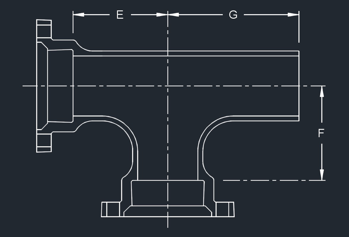 MJ xPE x MJASME B16.1 - Gray Iron Pipe Flanges and Flanged Fittings: Classes 25, 125, and 250 (Flange surfaces shall be faced and drilled in accordance with ANSI Class 125)
- AWWA C104/A21.4 - Standard for Cement-Mortar Lining for Ductile-Iron Pipe and Fittings for Water
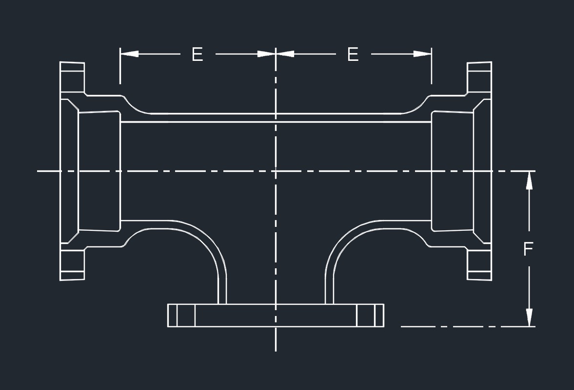 MJ x MJ x FLGAWWA C111/A21.11 - Rubber-Gasket Joints for Ductile-Iron Pressure Pipe and Fittings
- Ductile iron mechanical joint fittings 3" through 24" shall be rated for 350 PSI working pressure.
- Flanged ductile iron fittings in 24 inch and smaller sizes may be rated for 350 psi with the use of special gaskets.
- MJ - mechanical joint
- PE - plain end
- FLG - flange
![]()