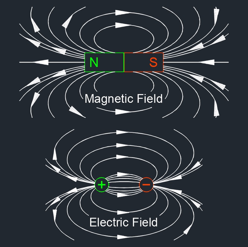
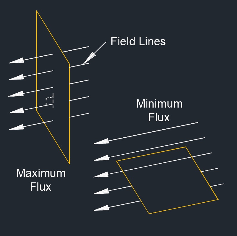
Magnetic flux, abbreviated as \(\Phi\) or \(\Phi_B\), is a measure of the total magnetic field that passes through a given area. The magnetic flux through a surface is defined mathematically as the product of the magnetic field passing through the surface and the surface area itself. Magnetic flux is a method that can detect wall thickness from corrosion and pitting without affecting the pipe. The magnetic flux through some surface is porportional to the number of field lines passing through that surface. This is essential in understanding electromagnetic induction, Faraday's law, and other phenomena related to the interaction between magnetic fields and electric circuits.
Magnetic Flux Formula |
||
|
\( \Phi_B \;=\; B \cdot A \) (Magnetic Flux) \( B \;=\; \dfrac{ \Phi_B }{ A } \) \( A \;=\; \dfrac{ \Phi_B }{ B } \) |
||
| Symbol | English | Metric |
| \( \Phi_B \) (Greek symbol Phi) = Magnetic Flux | \(Vs\) | \(Wb\) |
| \( B \) = Magnetic Field | \( G\) | \( T\) |
| \( A \) = Area Cross-section Perpendicular to Magnetic Field B | \(in^2\) | \(m^2\) |
Magnetic Flux Formula |
||
|
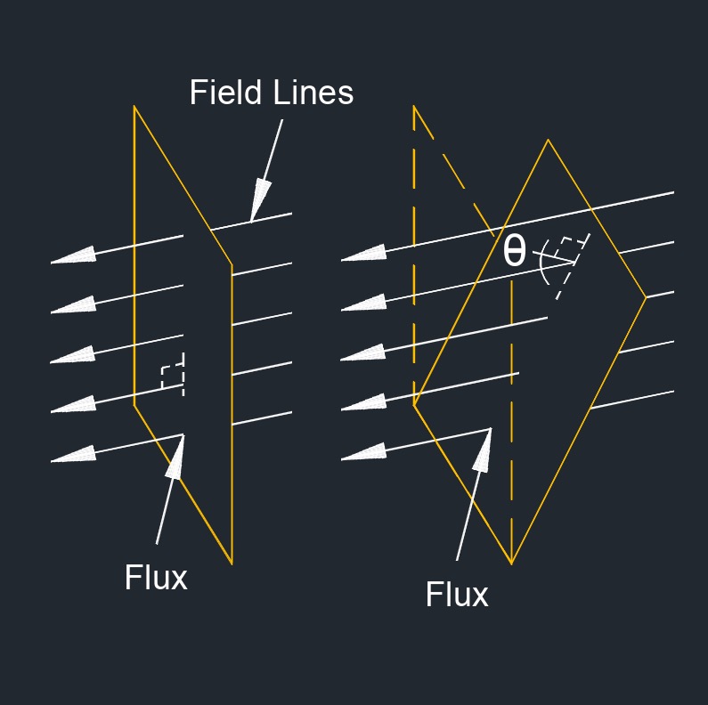
\( \Phi_B \;=\; B \cdot A \cdot cos(\theta) \) (Magnetic Flux) \( B \;=\; \dfrac{ \Phi_B }{ A \cdot cos(\theta) } \) \( A \;=\; \dfrac{ \Phi_B }{ B \cdot cos(\theta) } \) \( cos\;\theta \;=\; \dfrac{ \Phi_B }{ B \cdot A } \) |
||
| Symbol | English | Metric |
| \( \Phi_B \) (Greek symbol Phi) = Magnetic Flux | \(Vs\) | \(Wb\) |
| \( B \) = Magnetic Field | \( G\) | \( T\) |
| \( A \) = Area Cross-section Perpendicular to Magnetic Field B | \(in^2\) | \(m^2\) |
| \( \theta \) = Angle Between a Perpendicular Vector to the Area and the Magnetic Field | \(deg\) | \(rad\) |
The orientation of the magnetic field lines with respect to the surface through which the magnetic flux is being measured is a factor in determining the magnetic flux. The angle θ in the magnetic flux formula (Φ = B * A* cos (θ)) represents the angle between the magnetic field lines and the normal to the surface.
Understanding the orientation of the magnetic field lines is crucial in various applications, such as electromagnetic induction, where changes in magnetic flux induce an electromotive force (EMF) in a coil or conductor according to Faraday's law of electromagnetic induction.
![]()