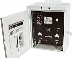
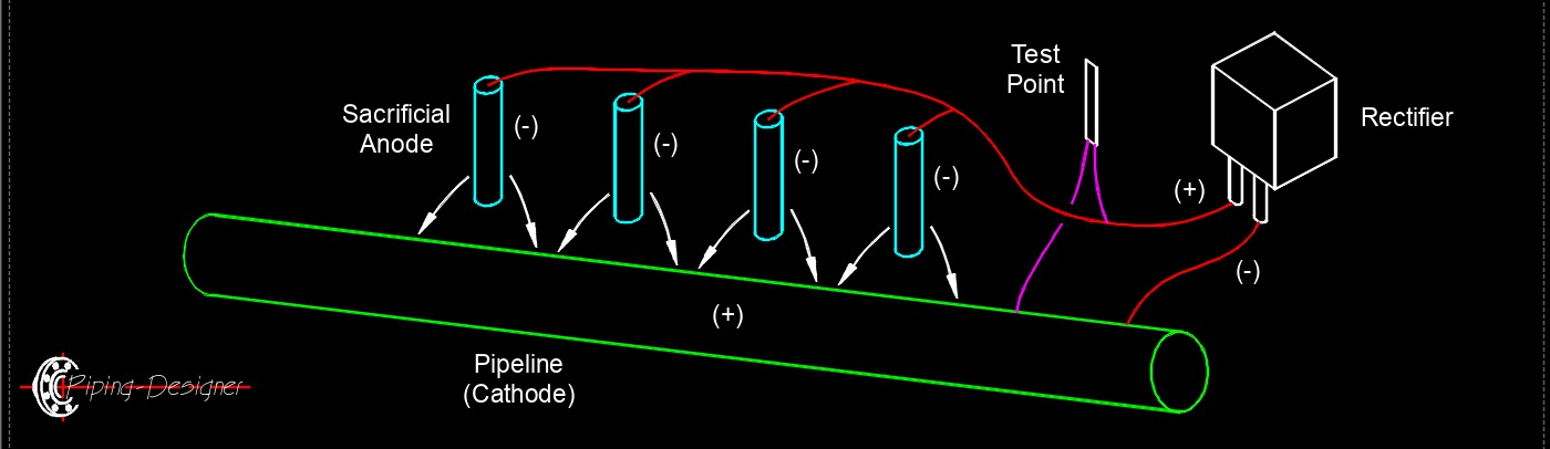
 Rectifier is an electrical device used in impressed current cathodic protection (ICCP) systems to prevent corrosion in metal structures like pipelines, storage tanks, and marine vessels. It converts alternating current (AC) from a power source into direct current (DC), which is then supplied to the impressed current anodes. These anodes, placed in an electrolyte such as soil or water, release the DC into the electrolyte, driving electrons to the protected structure to maintain it in a cathodic state, thus inhibiting corrosion. Rectifiers are adjustable, allowing precise control of the current output to match the protection needs of the structure and environmental conditions. They typically include components like transformers, diodes, and control circuits to ensure stable and efficient operation. Regular monitoring and maintenance of the rectifier are essential to ensure the ICCP system functions effectively.
Rectifier Types
Half-wave Rectifier - A fundamental electronic circuit that converts alternating current (AC) into pulsating direct current (DC). It does this by allowing only one half-cycle (either positive or negative) of the AC waveform to pass through, while blocking the other half-cycle. The core component of a half-wave rectifier is a diode. A diode is a semiconductor device that allows current to flow in only one direction (forward bias) and blocks it in the opposite direction (reverse bias). This process results in a pulsating DC output that consists only of the passed half-cycles of the original AC waveform.
Full-wave Rectifier - Is an electronic circuit that converts both the positive and negative half-cycles of an alternating current (AC) waveform into a pulsating direct current (DC) output. Unlike a half-wave rectifier, which only uses one half of the AC cycle, a full-wave rectifier utilizes the entire waveform, leading to a more efficient conversion and a smoother DC output. The core principle of a full-wave rectifier is to ensure that current flows through the load in the same direction during both the positive and negative half-cycles of the AC input. This is achieved using multiple diodes.
- Center-Tapped Full-Wave Rectifier - This type uses a center-tapped transformer and two diodes. The transformer has a secondary winding with a tap in the middle, effectively dividing the secondary voltage into two equal but opposite phase voltage.
- Bridge Full-Wave Rectifier - This type uses four diodes arranged in a "bridge" configuration and a standard (non-center-tapped) transformer.
Controlled Rectifier - An electronic circuit that converts alternating current (AC) to direct current (DC) and, crucially, allows for variable control of the output DC voltage. This ability to regulate the output distinguishes it from uncontrolled rectifiers (like those using only diodes), which produce a fixed DC output voltage. The key to controlled rectification lies in the use of thyristors, particularly Silicon Controlled Rectifiers (SCRs), instead of or in conjunction with diodes. Diodes are "uncontrolled" because they turn on automatically when forward-biased. Thyristors, on the other hand, require a small electrical pulse (a "gate signal" or "trigger pulse") applied to their gate terminal to turn on, even when they are forward-biased. This characteristic allows for precise control over when the device starts conducting during each AC cycle.
-
- Single-Phase Controlled Rectifiers -
- Half-Wave Controlled Rectifier - Uses a single thyristor. Only rectifies one half-cycle, leading to high ripple and low efficiency, but offers basic control.
- Full-Wave Controlled Rectifier (Center-Tapped) - Uses a center-tapped transformer and two thyristors. Provides full-wave rectification with control.
- Full-Wave Bridge Controlled Rectifier - Uses four thyristors in a bridge configuration. Most common type for single-phase, offering full-wave rectification and output control without a center-tapped transformer. Some bridge configurations can also use a mix of thyristors and diodes (e.g., "semi-converters" or "half-controlled bridge rectifiers").
- Three-Phase Controlled Rectifiers - Used for high-power industrial applications, employing three or six thyristors in various configurations (e.g., three-phase half-wave, three-phase full-wave bridge). These provide a smoother DC output and higher power handling capability.
- Single-Phase Controlled Rectifiers -
Three-phase Rectifier - Is an electronic circuit that converts a three-phase alternating current (AC) voltage into a direct current (DC) voltage. It's an essential component in power electronics, especially for applications requiring high-power DC supplies with minimal ripple. Unlike single-phase rectifiers that convert a single AC waveform, a three-phase rectifier utilizes three separate AC waveforms that are phase-shifted from each other (typically by 120 degrees). This results in a smoother and more consistent DC output with less ripple. The rectification process commonly uses a bridge configuration of six diodes (or thyristors for controlled rectifiers), two for each phase. Each diode is forward-biased and conducts when its anode voltage is higher than its cathode voltage. Three-phase rectifiers can be broadly categorized based on their control mechanism and circuit configuration.
- Uncontrolled Rectifiers (Diode Rectifiers) - These use diodes as the switching elements. Diodes are passive devices that allow current to flow in only one direction. They are simple and reliable but offer no control over the output voltage.
- Three-phase Half-wave Rectifier - Uses three diodes, one for each phase. It's the simplest type but has higher ripple and requires a neutral connection.
- Three-phase Full-wave Bridge Rectifier (Six-pulse Rectifier) - Uses six diodes, arranged in a bridge configuration. This is the most common type due to its lower ripple and higher efficiency compared to the half-wave.
- Controlled Rectifiers - These use controllable switching devices like thyristors (SCRs) instead of diodes. Thyristors allow for control over the firing angle, which in turn controls the output DC voltage. This is useful for applications requiring variable DC output.
- Twelve-pulse Rectifiers - For very high-power applications, two six-pulse bridge circuits can be connected in series with a 30-degree phase shift between their AC connections. This design further reduces harmonic distortion and ripple.
Precision Rectifier (Super Diode) - Is an electronic circuit that rectifies low-level AC signals with high accuracy, overcoming the limitations of traditional diode-based rectifiers. Unlike standard rectifiers, which suffer from the diode's forward voltage drop, precision rectifiers use operational amplifiers (op-amps) combined with diodes to achieve precise rectification, even for small signals below the diode's threshold. The op-amp compensates for the diode's voltage drop by providing gain and feedback, ensuring the output accurately reflects the rectified input signal.
- Half-Wave Precision Rectifier - Outputs only the positive (or negative, depending on configuration) portion of the input AC signal. The op-amp drives the diode to conduct without the usual voltage drop affecting the output.
- Full-Wave Precision Rectifier - Outputs the absolute value of the input signal, converting both positive and negative halves of the AC signal to a single polarity (usually positive). This is often achieved using a combination of op-amps and diodes in a bridge-like configuration
![]()