- See Article - Beam Design Formulas
Cantilever Beam - Load Increasing Uniformly to One End formulas |
||
|
\( R \;=\; V \;=\; W \) \( V_x \;=\; W\cdot \dfrac{ x^2 }{ L^2 } \) \( M_{max} \; \left(at\; fixed \;end \right) \;=\; \dfrac{ W\cdot L }{ 3 } \) \( M_x \;=\; \dfrac{ W\cdot x^3 }{ 3\cdot L^2 }\) \( \Delta_{max} \; \left(at\; free\; end \right) \;=\; \dfrac{ W\cdot L^3 }{ 15\cdot \lambda\cdot I }\) \( \Delta_x \;=\; \dfrac{ W\cdot x^2 }{ 60\cdot \lambda \cdot I \cdot L^2 } \cdot ( x^5 + 5\cdot L^4 \cdot x + 4\cdot L^5) \) |
||
| Symbol | English | Metric |
| \( R \) = reaction load at bearing point | \(lbf\) | \(N\) |
| \( V \) = maximum shear force | \(lbf\) | \(N\) |
| \( M \) = maximum bending moment | \(lbf-in\) | \(N-mm\) |
| \( \Delta \) = deflection or deformation | \(in\) | \(mm\) |
| \( W \) = total load \((w\;L\;/\;2) \) | \(lbf\) | \(N\) |
| \( w \) = highest load per unit length | \(lbf\;/\;in\) | \(N\;/\;m\) |
| \( L \) = span length of the bending member | \(in\) | \(mm\) |
| \( x \) = horizontal distance from reaction to point on beam | \(in\) | \(mm\) |
| \( \lambda \) (Greek symbol lambda) = modulus of elasticity | \(lbf\;/\;in^2\) | \(Pa\) |
| \( I \) = second moment of area (moment of inertia) | \(in^4\) | \(mm^4\) |
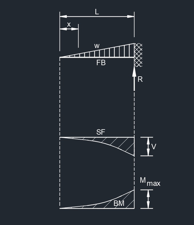
Diagram Symbols
Bending moment diagram (BMD) - Used to determine the bending moment at a given point of a structural element. The diagram can help determine the type, size, and material of a member in a structure so that a given set of loads can be supported without structural failure.
Free body diagram (FBD) - Used to visualize the applied forces, moments, and resulting reactions on a structure in a given condition.
Shear force diagram (SFD) - Used to determine the shear force at a given point of a structural element. The diagram can help determine the type, size, and material of a member in a structure so that a given set of loads can be supported without structural failure.
Uniformly distributed load (UDL) - A load that is distributed evenly across the entire length of the support area.
![]()