Orifice head loss, also called orifice pressure drop, is the pressure drop or decrease in fluid pressure caused by the presence of an orifice plate in a pipeline. It occurs due to the reduction in the flow area of the pipeline caused by the orifice plate, which results in increased fluid velocity and turbulence. The amount of head loss depends on several factors such as the size and shape of the orifice plate, the Reynolds number of the fluid flow, and the viscosity of the fluid. An orifice is a small, typically circular opening or hole in a pipe or vessel through which a fluid (liquid or gas) is allowed to pass. Orifices are commonly used in various engineering and industrial applications for purposes such as flow control, measurement, and restriction.
Horizontal Orifice and Nozzle Head Loss formula |
||
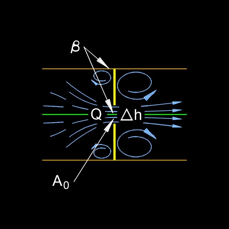
| \( \Delta h \;=\; \dfrac{ 1 }{ 2\cdot g } \cdot ( 1 - \beta^4 ) \cdot \left( \dfrac{ Q }{ C_d \cdot A_o \cdot Y } \right)^2 \) | ||
| Symbol | English | Metric |
| \( \Delta h \) = Head Loss | \( ft \) | \( m \) |
| \( g \) = Gravitational Acceleration | \(ft \;/\; sec^2\) | \(m \;/\; s^2\) |
| \( \beta \) (Greek symbol beta) = Ratio of Pipe Inside Diameter to Orifice Diameter | \( dimensionless\) | \( dimensionless\) |
| \( Q \) = Orifice Flow Rate | \(ft^3 \;/\; sec\) | \(m^3 \;/\; s\) |
| \( C_d \) = Orifice Discharge Coefficient | \( dimensionless \) | \( dimensionless\) |
| \( A_o \) = Orifice Area | \( in^2 \) | \( mm^2 \) |
| \( Y \) = Expansion Coefficient (Y = 1 for Incompressible Flow) | \( dimensionless \) | \( dimensionless\) |
Solve for: |
||
|
\( Y = C_{d,c} \;/\; C_{d,i} \) \( C_{d,c} \) = discharge coefficient compressible fluid \( C_{d,i} \) = discharge coefficient incompressible fluid \( \beta \) (Greek symbol beta) = \(d_0 \;/\; d_u\) \( d_o \) = orifice or nozzle diameter \( d_u \) = upstream pipe inside diameter from orifice or nozzle |
||
When Fluid Flows Through an Orifice, Several Factors Contribute to the Loss of Pressure
The magnitude of the pressure drop or head loss depends on various factors, including the size and shape of the orifice, the properties of the fluid (density and viscosity), and the flow rate of the fluid. Engineers use mathematical equations and empirical data to calculate orifice head loss, which is important for designing systems where maintaining a specific pressure or flow rate is critical. Orifices are commonly used in applications such as flow meters, control valves, and pressure-reducing devices. Understanding and accurately calculating orifice head loss is essential for optimizing the performance of these systems and ensuring that they operate within specified parameters.
![]()
Vertical Orifice and Nozzle Head Loss formula |
||
| \( \Delta h \;=\; \dfrac{ 1 }{ 2\cdot g } \cdot ( 1 - \beta^4 ) \cdot \left( \dfrac{ Q }{ C_d \cdot A_o \cdot Y }\right)^2 - \Delta y \) | ||
| Symbol | English | Metric |
| \( \Delta h \) = Head Loss | \( ft \) | \( m \) |
| \( g \) = Gravitational Acceleration | \(ft \;/\; sec^2\) | \(m \;/\; s^2\) |
| \( \beta \) (Greek symbol beta) = Ratio of Pipe Inside Diameter to Orifice Diameter | \( dimensionless \) | \( dimensionless\) |
| \( Q \) = Orifice Flow Rate | \(ft^3 \;/\; sec\) | \(m^3 \;/\; s\) |
| \( C_d \) = Orifice Discharge Coefficient | \( dimensionless \) | \( dimensionless\) |
| \( A_o \) = Orifice Area | \( in^2 \) | \( mm^2 \) |
| \( Y \) = Expansion Coefficient (Y = 1 for Incompressible Flow) | \( dimensionless \) | \( dimensionless\) |
| \( \Delta y = ( \Delta y = y_1 - y_2 )\) = Elevation Change | \( dimensionless \) | \( dimensionless\) |
Solve for: |
||
|
\( Y = C_{d,c} \;/\; C_{d,i} \) \( C_{d,c} \) = discharge coefficient compressible fluid \( C_{d,i} \) = discharge coefficient incompressible fluid \( \beta \) (Greek symbol beta) = \(d_0 \;/\; d_u\) \( d_o \) = orifice or nozzle diameter \( d_u \) = upstream pipe inside diameter from orifice or nozzle |
||