Lap joint flange, abbreviated as \(LJF\), is a flange that consists of two parts, a stub end and the backing flange. On drawings, it can be abbreviated as LJF. On a Lap Joint, the flange slides over the pipe and the stub end is the connection where the gasket sits. The end where the gasket sits is the same outside diameter as the face of a raised face flange. In general, the thickness of the hub is between ¼” to 3/8”.
Lap Joint Flange Datasheets
| |
|---|---|
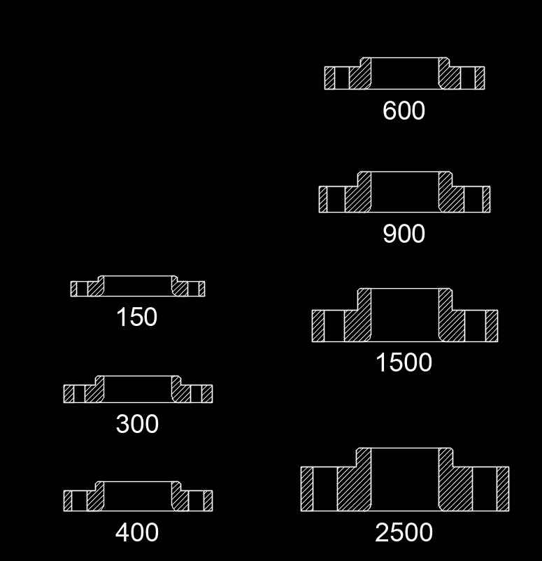
| Class | Flat Face |
| ANSI 150 | Lap Joint, ANSI Class 150 (in) |
| ANSI 300 | Lap Joint, ANSI Class 300 (in) |
| ANSI 400 | Lap Joint, ANSI Class 400 (in) |
| ANSI 600 | Lap Joint, ANSI Class 600 (in) |
| ANSI 900 | Lap Joint, ANSI Class 900 (in) |
| ANSI 1500 | Lap Joint, ANSI Class 1500 (in) |
| ANSI 2500 | Lap Joint, ANSI Class 2500 (in) |
The flange can be rotated which can be useful when fixing issues with bolt hole alignment. When designing a piping system, lap joint flanges should not be considered solely to alleviate poor alignment during construction. Good design practice should not need to include poor construction quality. However, if the piping needs to be frequently dismantled for inspection or cleaning, consideration should be made for lap joint flanges. They give the ability to swivel flanges and to align bolt holes which simplifies the assembly of large diameter or unusually stiff piping.
Lap joint flanges are usually used in low pressure applications and are not suitable when there are high loads on the flange pair. Some types of piping require the use of lap joint flanges. For example, metallic pipe that has been plastic lining may have lap joint flanges.
Using lap joint flanges might be an option for saving costs when the piping is made of exotic materials. By using a lap joint flange, the wetted materials would consist of the exotic materials and the flange would be carbon steel. Since the flange doesn’t ever come in contact with the process fluid, it would not be affected by the fluids.
Dimensions on the lap joint flange are similar to weld neck, slip-on or socket weld flanges. The backing flange has the same number of bolt holes, size and thickness of a weld neck or slip on flange.
Stub Ends
There are three different types of stub ends, Type A, B and C. Type A stub ends are machined to fit in a standard lap joint backing flange. The mating surfaces are shaped with the same profile to allow for uniform loading of the flare face. Type B stub ends are ends that are designed to be used with a standard slip on flange. Both Type A & B stub ends are either cast or forged.
Type C ends are designed to be used with either a lap joint flange or a slip on flange. Type C ends are fabricated from pipe. The most common type of fabrication is through the use of a machine flare. This is done by using a machine to flare the end of the pipe and then cutting it to length.
The stub end is available in two separate lengths, a short pattern and a long pattern. Long pattern ends are also known as ASA Stub Ends. Short pattern ends are used with larger flanges for ANSI 300 & 600. They generally are used for most sizes ANSI 900 & above.
![]()